
Robot welding seam tracking is a control method that allows a welding robot to detect joint position changes and automatically correct its path during welding. Instead of blindly following a taught program, the robot uses seam tracking data to stay aligned with the actual weld joint in real time. The most common approaches are through-arc seam tracking (TAST), tactile probe tracking, and laser vision seam tracking.
Seam tracking is necessary because real welded parts rarely match the programmed path perfectly. Joint position can shift due to fit-up variation, fixture error, thermal distortion, or part-to-part inconsistency. In heavy fabrication, even small deviations can cause lack of fusion, undercut, or missed welds if the robot does not adjust.
This article explains how robotic seam tracking works, compares TAST, tactile, and laser vision systems, and shows which method is best for carbon steel, aluminum, stainless steel, thin-gauge materials, and high-speed automated welding.
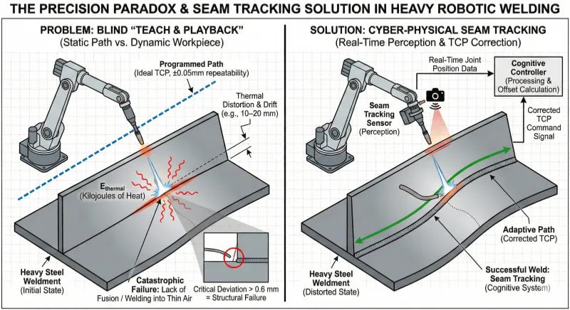
Through-Arc Seam Tracking (TAST)
Through-Arc Seam Tracking (TAST) is the industry standard for heavy carbon steel fabrication because it is essentially “free”—it requires no external optical sensors, only software enabled on the robot controller.
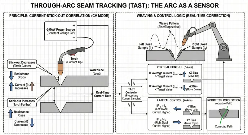
How TAST Works: The Arc as a Sensor
TAST utilizes the physics of the welding arc itself. In standard Gas Metal Arc Welding (GMAW), the power source operates in Constant Voltage (CV) mode. The electrical current (I) correlates directly with the contact tip-to-work distance (stick-out).
- Stick-out decreases (Torch gets closer): Resistance drops, Current increases.
- Stick-out increases (Torch moves away): Resistance rises, Current decreases.
To find the joint center, the robot weaves (oscillates) the torch in a sine or trapezoidal pattern. It samples the current at the left and right sidewalls of the groove.
- Vertical Control: If the average current is too high, the torch is too close; the robot biases up (+Z).
- Lateral Control: If the current is higher on the left dwell than the right, the robot biases the path to the left (−Y) to recenter.
Pros and Cons
- Best For: Heavy carbon steel plates (>3 mm thick) with distinct V-groove or Fillet geometries.
- Limitations:
- Aluminum: TAST often fails on aluminum. Aluminum is so conductive that changes in stick-out produce negligible changes in resistance, resulting in a poor Signal-to-Noise Ratio (SNR).
- Speed: The robot must weave to sense the wall. This limits travel speed (typically < 35–40 inches per minute).
- Thin Gauge: Cannot track on materials < 2 mm because the weave motion may burn through the sheet.
Tactile Seam Tracking Systems
Before vision systems matured, tactile probes were the only option for non-conductive tracking. They remain the dominant technology for Submerged Arc Welding (SAW).
How Tactile Tracking Works
A mechanical probe (stylus) rides inside the joint 50–100 mm ahead of the welding torch. The probe is physically linked to a motorized cross-slide. As the joint curves, the probe is pushed laterally, and transducers convert this displacement into corrective motor signals for the cross-slides.
The SAW Niche
In Submerged Arc Welding, the arc is buried under a mound of granular flux. Optical sensors (lasers) are blinded by the flux dust, and TAST is sluggish due to the massive weld pools. Tactile probes are immune to these issues because they rely on physical contact, making them ideal for pressure vessel and pipe manufacturing.
Limitations
- Wear: Probe tips are consumables and wear down quickly on abrasive oxide layers.
- Tack Welds: If the probe hits a tack weld, it “climbs” over it, potentially lifting the torch out of the joint and ruining the weld.
Laser Vision Seam Tracking
Laser vision represents the highest tier of accuracy and is essential for high-speed welding, aluminum, and thin-gauge materials where TAST and Tactile fail.
How Laser Vision Tracking Works
Laser vision seam tracking uses a projected laser line and an angled camera to scan the weld joint ahead of the torch. By analyzing the shape of the laser line, the system can calculate seam position, misalignment, gap changes, and joint geometry in real time, then send correction data to the robot controller.
The Physics: Optical Triangulation
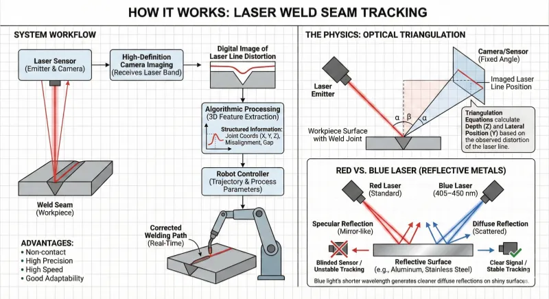
The sensor projects a laser line onto the part. A camera, mounted at a fixed angle, observes the line’s distortion. Using triangulation equations, the sensor calculates the depth (Z) and lateral position (Y) of the joint profile.
- Red vs. Blue Laser: Standard sensors use red lasers. However, for reflective metals like aluminum or stainless steel, red light can reflect specularly (like a mirror), blinding the sensor. Blue laser sensors (405–450 nm) generate cleaner diffuse reflections on shiny surfaces, ensuring stable tracking on aluminum battery trays or stainless tanks.
Look-Ahead Compensation
Because the sensor is mounted 20–50 mm ahead of the torch (to avoid heat damage), it sees the “future” path. The system uses a circular buffer to store the correction vector and applies it only when the TCP reaches that specific point on the part.
Beyond Tracking: Adaptive Process Control
Tracking only fixes the position of the weld. But what if the gap widens?
If a V-groove expands from a 2 mm gap to a 4 mm gap, maintaining the same path and speed will result in an underfilled, concave weld. Adaptive Process Control (Level 3 Control) uses the geometric data from the vision sensor to adjust welding parameters in real-time.
Volumetric Compensation Logic:
| Detected Condition | Adaptive Response | Result |
| Gap Widens (↑) | Decrease Travel Speed (↓) | Increases heat input per inch. |
| Gap Widens (↑) | Increase Wire Feed Speed (↑) | Deposits more filler metal to fill volume. |
| Gap Widens (↑) | Increase Weave Amplitude (↑) | Bridges the wider gap to fuse sidewalls. |
This capability effectively eliminates manual rework for variable fit-up.
TAST vs Tactile vs Laser Vision: Which Seam Tracking Method Is Best?
Selecting the right sensor depends on your material and cycle time requirements.
| Feature | TAST (Through-Arc) | Tactile (Probe) | Laser Vision |
| Cost | Low (Software only) | Medium ($10k–$15k) | High ($30k–$60k) |
| Primary Material | Carbon Steel | Pressure Vessels / Pipe | Aluminum, Stainless, Thin Sheet |
| Speed Limit | Slow (< 40 IPM) | Medium | Fast (up to 200 IPM) |
| Thin Gauge (<2mm) | No (Burn-through) | No (Probe force) | Yes (Excellent) |
| Aluminum | No (Conductivity issues) | Yes | Yes (Blue Laser recommended) |
| Main Advantage | Robust, zero maintenance | Immune to flux/dust | High precision, adaptive control |
What Is the Difference Between a Seam Tracking Sensor and a Seam Tracking System?
A seam tracking sensor is the sensing device that detects the actual position of the weld joint. Its job is to collect tracking data such as joint location, lateral deviation, height variation, gap size, or seam geometry and send that information to the control system. Depending on the technology used, the sensor may rely on welding current feedback, mechanical contact, or laser vision to identify where the seam is in relation to the torch.
A seam tracking system is the complete working solution built around that sensing function. It usually includes the sensor, signal processing or control software, communication with the robot controller, path correction logic, and in some cases adaptive process control. In other words, the sensor detects the seam, while the system turns that detection into real-time motion correction and stable weld quality.
The difference matters in real production. A sensor on its own does not guarantee successful tracking unless it is properly integrated with the robot, welding process, and controller response. For example, a laser seam tracking sensor may scan the joint accurately, but the full seam tracking system must still calculate the correction, buffer the data, and apply it at the right moment as the torch reaches that position.
In practical terms, buyers often use the two terms interchangeably, but they are not exactly the same. If you are comparing equipment, the sensor refers to the detection hardware, while the system refers to the full tracking package that makes robotic welding correction possible.
Seam Tracking Sensor vs Seam Tracking System
- Seam tracking sensor: Detects seam position and joint variation.
- Seam tracking system: Combines the sensor, software, controller communication, and correction logic.
- Sensor = detection hardware
- System = complete tracking solution
How to Choose a Seam Tracking System for Welding
The right seam tracking system depends on your material, joint type, welding speed, and production environment. For heavy carbon steel fabrication, TAST is often the most practical lower-cost option because it does not require an external optical sensor. For submerged arc welding and applications with heavy flux or poor optical visibility, tactile tracking remains a reliable choice. For aluminum, stainless steel, thin-gauge parts, and high-speed automated welding, laser vision systems are usually the best solution because they provide faster, more precise, and non-contact seam detection. If joint gap and fit-up vary significantly from part to part, an adaptive laser vision system is generally the most capable option.
ROI of Robot Welding Seam Tracking Systems
While a laser system requires a higher upfront investment (~$50k–$100k), the ROI is typically realized in 18–24 months through two main avenues:
- Fixture Savings: You can use simple clamps instead of precision-machined, heavy-duty fixtures. The sensor compensates for the “slop” in cheaper tooling.
- Scrap Reduction: Reducing defect rates from ~5–10% to under 1% significantly lowers the cost per part, specifically by eliminating post-weld grinding and re-welding labor.
FAQ
A: Generally, no. Aluminum’s low electrical resistance means changes in stick-out do not create a strong enough change in welding current for the robot to detect reliably. Laser vision is the standard for aluminum.
A: TAST requires weaving, which limits speed. Laser vision systems, however, can track at speeds exceeding 200 inches per minute (85 mm/s), often faster than the welding process itself allows.
A: Seam Finding is a static search before the arc starts (using touch or laser) to shift the entire path. Seam Tracking is dynamic correction during the weld to compensate for thermal distortion occurring in real-time.